Trenholme Junction layout plan
Notes
There has many requests, made from the comments on the YouTube channel, for a track plan of Trenholme Junction. In the past I resisted the temptation to produce one. I didn't start off with a track plan when I built the layout. There was a list of features the layout would include and these were on a simple list.
I wanted people to travel the trains and take the journeys, just like I did when I was a child. Each time I was asked, I answered, ride the trains, especially the DMU cab rides and you would discover the routes and places.
Imagine my surprise when somebody wrote to me and said he had done just that AND he'd drawn a track plan based on many hours taking the journeys'. When Dave Bernard sent me the plan I was even more astonished that it was probably about 90% accurate. There has been some adjustments made and the plan is what is available here. Its not dead to scale, but then it doesn't have to be, the components in the right places is more important.
For those of you who have read the rest of this blog, some bits will be repeated, sorry about that.
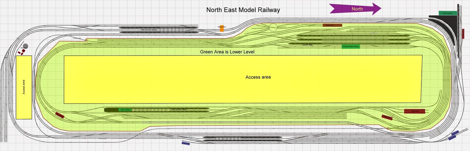
There are two large ovals, each four roads wide, one on the lower level and one on the upper. The passenger roads are the inner pair on the lower level and the outer pair on the upper. There are five stations, two on the lower and three on the upper. Two tunnels connect the levels together together with a long incline which can be seen in full, over 40 feet long.
There are Marshalling Yards on each level, the lower can store 400 wagons plus another 100 in the reception dispatch road.
Stations
None of the stations are named, this is deliberate. I wanted representative types of stations on the layout, not actual replicas of the real thing. Reference to each one by geographical location, 'Main' being the exception.
The Main Station (lower) has five full length platform faces and two bay platforms, one at the north end and one at the south. The full length platforms can accommodate eighteen coach trains. There is a station avoidance road to the west which allows trains to pass through the station through to the branch without passing the platforms.
The carriage sidings are situated to the west and south sides of the station.
The North Station (upper) is has the most complicated junction and is the branch end. The curved platforms serve the passenger carrying through roads and the straight platform is the termination of the branch. Provision has been made for the branch to continue into the next room where a terminus on the scale of Whitby Town was intended to be built. Single track would continue from the end of this station and a double track from the lower level under the station would join the new terminus. It's unlikely this terminus will be built.
The West Station (upper) has two through roads and a bay platform. The bay platform can be accessed only from the south junction and the train has to reverse direction to continue its journey. The run round loop is also the head shunt for the pit sidings.
The East Station (upper) is both a through station for the main line and also has one platform face on the branch line. The branch line platform face also serves as the head shunt for the upper marshalling yard.
The South East Station (lower) is very similar to South Bank where I grew up and has two main line platform faces. I added a bay to one end to give more operational possibilities.
Layout Plan
The plan is free to copy or download and if you wish, you may use any part of it.
Do please bear in mind to attribute the work of producing the plan to Dave Bernard (who is an English teacher in Bolivia) and add my link (below) to any article you publish using any of the information.
Link:- https://www.youtube.com/user/dougattrenholmebar
The plan has been produced using Anyrail5 which can be downloaded free of charge and allows you to view it, however, to modify it you will need to purchase a licence.
David has used some components in the track plan for convenience and it should noted that all track on the 'real' layout is Peco Streamline Code 100. The points (switches) are a mixture of both insulfrog and electrofrog. He used a minimum radius of three feet for the curves, this adds a neatness to the drawing, maybe some of the real ones are a little tighter.
To download the picture - no software to view required click this link:-
https://www.btcloud.bt.com/?shareObject=60fbfca8-8a42-6e95-c136-686ee1acec05
To download the Anyrail5 file click this link:-
https://www.btcloud.bt.com/?shareObject=6f88e3e2-ade4-e831-b873-7308ed405a01
Thank you David for a superb job. Doug
Thanks to Doug and Dave, Jim
ReplyDeleteThanks for the plans. Now to fit it into a space which is 60' wide by 120' long; with a 20' ceiling. I have an empty room, in a building, which is not being used for anything; so this plan will, with appropriate modifications, should work out quite well. Thank you.
ReplyDeleteWhere are you in the world?
DeleteThe North Station is currently the branch end. It was intended to carry on the branch to a terminus based on Whitby Town. You have enough space to do this if you wish. Just a thought, let me know what you do with it.
ReplyDeletehello, how long is the room in which the layout is based
ReplyDeleteIts about a foot longer longer than the plan and two foot wider. Each square is the plan if one foot
Deletehave you made a vid showing wide angle views of layout? would love to see that. and details of controls etc.
ReplyDeleteHi Doug, just tried to download both BTCloud files but there was an error. The page you requested cannot be found.
ReplyDelete